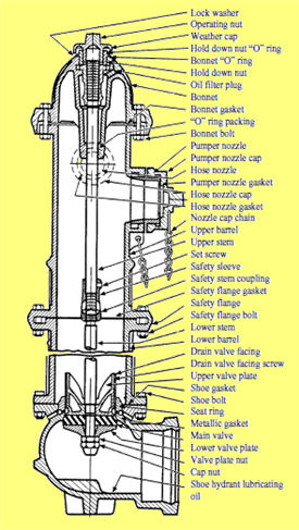
The user attaches a hose to the fire hydrant then opens a valve on the hydrant to provide a powerful flow of water on the order of 350 kpa 50 pounds per square inch gauge psig this pressure varies according to region and depends on various factors including the size and location of the attached water main.
Fire hydrant valve diagram.
Trumbull has over 25 years experience in the manufacturing of fire hydrant repair parts.
Numerous dry and wet barrel designs are available that meet stringent ul fm requirements some with maximum working pressures of 350psi full line catalog.
The k81 dd utilizes a light weight ductile iron upper barrel to allow for a single man repair.
As one of the world s largest manufacturers of fire hydrants gate valves swing check valves and tapping sleeves we are pleased to serve you.
Reinforced rubber main valve and rugged drain valve assembly.
A fire hydrant system block plan is an indelible diagram mounted within the booster cabinet pump room and fire control room that illustrates the primary features of the fire hydrant system including the water supply location dimensions location capacity of each water storage or tank location quantity of each valve location of each.
Since 1875 the eddy hydrant has been reliably serving communities and firemen across the country.
Production facilities are located in beaumont texas and south st.
Extra seals to protect against corrosion.
Inquire for minimum quantities and availability of specific parts.
This user can attach this hose to a fire engine which can use a powerful pump.
Ap smith h200 h205.
Fire hydrant year of manufacture main valve opening size catalog number hydrant styles 2014 present 4 1 2 a 421 hp 3 way 5 1 4 a 423 hp 3 way mueller albertville ala year of manufacture main valve opening size 350 wp awwa fire main hydrant and 584 n is cast on barrel between groundline flange and bonnet.
Positive stop prevents unintentional damage from over torquing during opening.
American flow control serves the united states and the world with its vast selection of valve and hydrant products.
5br250 hydrant 4 bury 15 16 square 2 2 1 2 nst 4 1 2 nst nozzle red pe connection open left 2 auto drains 6 ol valve ej 5br250 hyd 4 0 pe 2ad vlv product 51536d.
Submittal sheets eddy hydrant.
Backed by over 100 years of hydrant design know how the k81 d has been carefully engineered for rugged durability and longer life.
The kennedy guardian k81 dd fire hydrant was developed in april 2014.
As a critical piece of any emergency response system used to preserve lives and property all mueller fire hydrants are designed built and tested to assure high performance long life and dependability.
The eddy opens easily and quickly under pressure ensuring time tested performance year after year.


